
UH-60 / HH-60 Black Hawk
Military AITB module transitions from the field-grade scissor lift undercarriage into an aircraft floor track receiver for medevac transport.
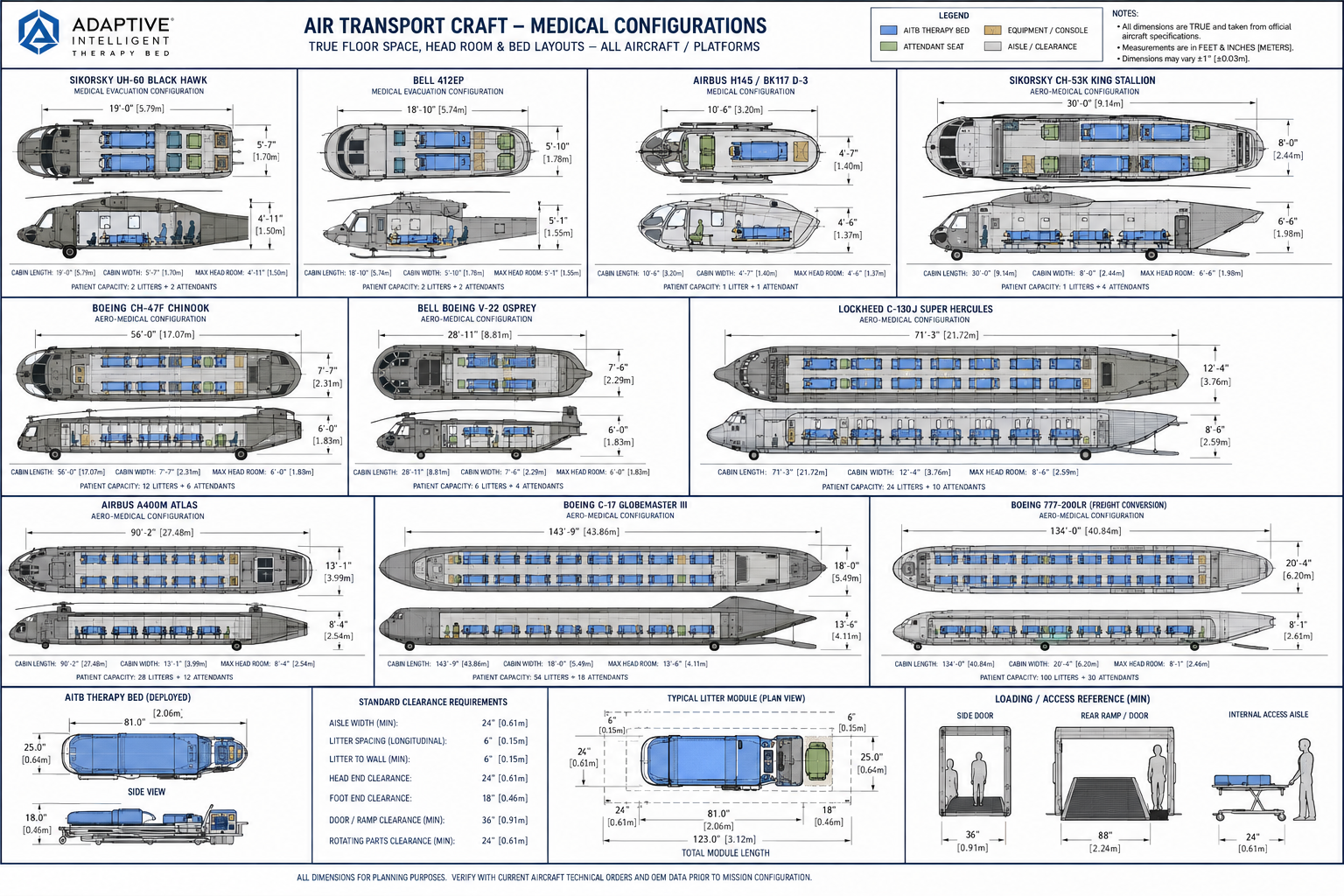
Transport platform planning
Reference planning page for AITB bed footprint, loading paths, usable cabin space, undercarriage systems, aircraft floor tracks, civil medical movement, and aircraft-specific adapter kit concepts.
Candidate transport classes
AITB aircraft integration planning is based on a platform-family approach: the AITB patient module remains standardized while aircraft, helicopter, ambulance, and facility environments receive adapter frames, receiver assemblies, restraint systems, and service interface kits.
Platform transition scenarios
Each scenario below shows a single full-size adult patient lying flat inside the AITB module. The military system uses an army-green field-grade scissor lift chassis and aircraft floor track interface. The civil system uses a stainless-steel hospital chassis with a hospital-blue AITB module for smooth movement through clinical corridors, ICU pathways, and rooftop helipad transfers.
Military AITB module transitions from the field-grade scissor lift undercarriage into an aircraft floor track receiver for medevac transport.

Heavy-lift loading/offloading with elevated chassis alignment and positive lock interface between the module base and aircraft receiver track.
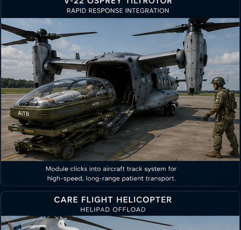
Rapid-response integration where the AITB module is secured to a mission-configured aircraft track assembly for high-speed medical movement.
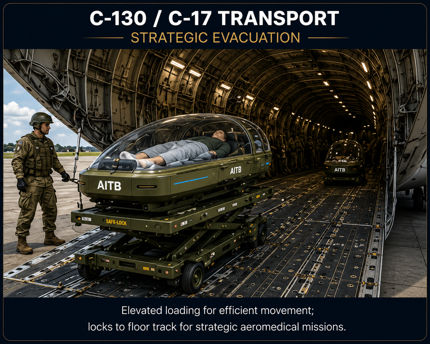
Strategic evacuation layout with military module, field-grade lift chassis, aircraft restraint points, and wide cargo-floor loading path.
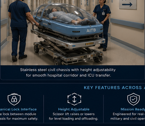
Hospital-blue civil AITB on a stainless-steel clinical chassis for corridor, elevator, ICU, emergency department, and step-down movement.
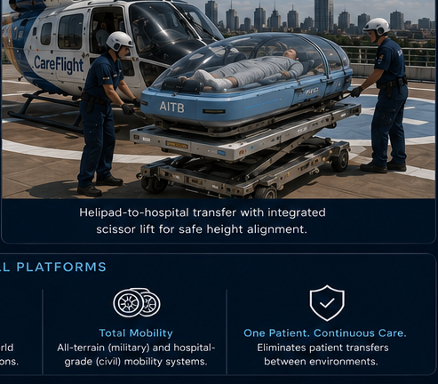
Civil rooftop transfer scenario with integrated height-adjustable chassis, helipad-to-hospital movement, and uninterrupted patient monitoring.
Human factors and sizing assumptions
AITB integration should be validated against a full-size adult human envelope, not a reduced occupant figure. The design basis below keeps a single adult patient lying flat, with sufficient shoulder clearance, foot clearance, restraint access, medical tubing paths, dome clearance, and caregiver reach.
Planning values for full-size adult male and female patient compatibility.
| Adult male planning range | 5 ft 6 in to 6 ft 4 in height; approximately 150 to 260 lb standard planning range, with bariatric upgrade pathways above this range. |
|---|---|
| Adult female planning range | 5 ft 1 in to 6 ft 0 in height; approximately 110 to 220 lb standard planning range, with bariatric upgrade pathways above this range. |
| Single-patient rule | AITB module holds one patient only. It is not a two-patient capsule. |
| Patient posture | Supine, lying flat, full body supported from head through feet, with restraint, airway, IV, and monitoring access. |
| Recommended patient surface length | Approximately 84 to 90 in usable patient support surface to accommodate tall adult patients plus foot clearance. |
| Recommended patient surface width | Approximately 28 to 32 in usable patient surface width, with wider clinical or bariatric variants requiring separate aircraft compatibility validation. |
Planning compatibility for medevac aircraft, civil rotorcraft, and hospital movement.
| UH-60 / HH-60 usable cabin class | Approx. 11 ft usable cabin length class, approx. 7 ft cabin width class, and low cabin height that requires a low dome and side-access strategy. |
|---|---|
| V-22 / CH-47 / C-130 / C-17 fit logic | Larger loading paths support scissor lift and floor-track transfer, but final restraint, vibration, power, oxygen, suction, and egress must still be aircraft-specific. |
| Civil medevac rotorcraft fit logic | AW139, H145, Bell 412, and Bell 429 classes require strict door, stretcher path, and cabin turning validation before any fixed dimension can be treated as final. |
| Hospital corridor logic | Civil AITB must negotiate standard medical corridors, ICU doorways, service elevators, and emergency department turns using a compact stainless clinical chassis. |
| Height alignment | Both civil and military chassis use height-adjustable lift geometry so the AITB module can align to aircraft floors, ambulance decks, hospital beds, or docking stations. |
AITB module and chassis specification sheets
Combat medevac, tactical aircraft loading, field mobility, and hardened patient protection.
| Module role | Protected one-patient critical-care capsule for field extraction, medevac aircraft loading, forward care, and tactical transport. |
|---|---|
| Exterior module length target | Approx. 100 to 108 in planning target, balancing tall adult patient fit with aircraft cabin length limits. |
| Exterior module width target | Approx. 34 to 38 in planning target for aircraft clearance and medic access. |
| Exterior installed height target | Approx. 42 to 48 in with low-profile dome for aircraft headroom constraints. |
| Dome and shell | Military-grade transparent ballistic dome concept with protective lower shell using Kevlar/composite or equivalent survivability architecture. |
| Power | Rechargeable independent mission power with hot-swap battery strategy and aircraft/facility power interface. |
| Chassis interface | Army-green all-terrain scissor lift chassis with a female cradle receiver that mechanically locks to the rounded male base of the AITB module. |
| Aircraft interface | Module can detach from ground chassis and lock into aircraft floor track or mission receiver assembly. |
Hospital, ICU, ambulance, helipad, infectious isolation, rehabilitation, and therapeutic care continuity.
| Module role | One-patient therapeutic care capsule optimized for hospitals, civil medevac, ambulance transfer, ICU rooms, and recovery environments. |
|---|---|
| Exterior module length target | Approx. 100 to 108 in planning target with full adult foot clearance and therapy module space. |
| Exterior module width target | Approx. 32 to 36 in planning target for hospital corridors, ICU doors, and elevator movement. |
| Exterior installed height target | Approx. 42 to 48 in, with lower dome arc than military renderings where clinical access and corridor clearance dominate. |
| Dome and shell | Clinical transparent enclosure, not ballistic. Civil model does not use a Kevlar base or bulletproof dome. |
| Power | Facility power with uninterrupted backup battery for transfer, monitoring continuity, short transport, and emergency movement. |
| Chassis interface | Hospital-blue module installed into stainless-steel height-adjustable chassis with low-noise hospital casters and female cradle receiver. |
| Therapy systems | Thermal nodes, vibration capsules, pressure redistribution, biometric monitoring, airflow, telehealth, and diagnostic plug-in modules. |
The patient module is sized around aircraft cabin classes and then transferred from the scissor lift chassis to a floor-track receiver. This avoids trying to carry the entire ground mobility base inside smaller aircraft.
The undercarriage functions as a height-adjustable mechanical interface: lift, align, cradle, lock, lower, and transfer. It is a transport chassis, not a passive push cart.
Military AITB prioritizes survivability, independent power, field mobility, and aircraft loading. Civil AITB prioritizes corridor movement, ICU docking, therapeutic systems, stainless construction, and backup power.
Integration engineering review
Final integration requires mockup testing, engineering review, airworthiness evaluation, medical human-factors review, electrical safety review, vibration testing, and mission configuration validation.
| Integration Area | Planning Focus | Review Requirement |
|---|---|---|
| Floor Securement | Receiver frame and aircraft tie-down interface | Aircraft technical order and airworthiness review |
| Headroom / Access | Dome opening envelope and caregiver reach | Cabin mockup validation |
| Loading Path | Ramp or side-door clearance, turning radius, loading aids | Platform-specific human factors review |
| Utilities | Power, oxygen, suction, data, monitoring | Clinical and aviation electrical safety review |
| Vibration / Shock | Aircraft vibration isolation and patient protection | MIL-STD vibration and restraint testing pathway |
| Emergency Egress | Patient access, release handles, crew movement, evacuation path | Crew workflow and safety validation |